Since I wrote last here my interest in microprocessors and embedded in general has been constantly growing. I have dabbed into designing my own PCBs getting them fabricated and soldering SMD components on them.
The Story
I live on a small island in north of Scotland, and I fell in love with sailing from the first week we moved here in 2017. Our local sailing club is more than a hundred years old. We sail traditional Westray Skiff (made only on the Island) pictured below (I promise my friend is not grumpy because of me). If you are interested see more photos and island life visit The hall of Einar blog.

With my friend on Westray regatta day
Turns out a long tradition comes with, well Long Traditions ™! During the summer months we go out in the water twice a week. As a starting mechanism club uses a wooden race starter board with white flaps and starter gun or a compressed air horn if gun is not working. The sequence as follows:
- Warmup shot
- Random pause between 30 to 60 seconds
- Timer Start shot (three minutes to start the race)
- Three white flaps close one by one at one minute interval
- Race Start shot
The timekeepers sit on the pier while the starting board faces the sea, so sailors can see it from the distance and position their boats in the best position possible before the start line at the final shot (horn).
What are we building?
So the idea is to make an electronic version of the board mentioned above. We will use led lights for white flaps (visual clue to the time for sailors) and a truck horn for sounds. For the digital logic there are a lot of options, from RaspberryPI to Arduino and many other developer boards in between i.e stm32 blue/black pills. I could have used any of them to achieve this, in fact prototyping of the idea was done on a STM32 Blue Pill on a breadboard.
Instead, I decided to design a custom PCB for this specific purpose. This helped me to learn a ton about electronics, MCU s, deciphering datasheet , designing small buck converters , MOSFETS , KiCad and PCB fabrication ordering etc. I have thoroughly enjoyed every bit of it.
Project Requirements:
- Two user input buttons to start and stop the timer, additionally we’ll also have same buttons extend to common garage door remote controller with
433MhzRadio Frequency Module (legal in the UK). - Three controlled 12v DC power outputs for large LED light arrays.
- One controlled 12v DC power output for a Horn for audio signal.
- User must be able to start the timer from idle position, and cancel at any stage by the stop button when in running stage.
- Start and Stop has a distinguishable horn sound for the sailors to get clear indication on what is happening.
- Start or Stop button do not have any effect when in Running or Idle state respectively to prevent accidental errors.
- Warmup period between when the start button was pressed and three minute countdown start must be a reasonable random time between 30-60 seconds.
- After the timer has taken a full course it goes back to idle stage and can be used to start the next race without any kind of reset.
Basic idea
Basic Idea is very simple, we have a microcontroller that takes signals from start and stop buttons, keeps accurate (depends on the crystal quality) time and runs the sailing starter procedure. It would turn the Horn and light on/off according to the stage of the process and
Bob’s your uncle
(an’ Fanny’s yer aunt).
But we can’t hang an MCU in the air and certainly can’t power it up by a 12V Car battery, we also need to drive the horn and the LED lights with appropriate voltage and current. It would also be nice to have it operate remotely, so on the short staff days someone from the sailing boat can operate it. (we need to make sure they can’t abuse it by starting the race when they are in a more favourable position).
The MCU I chose was
STM32f103C6
its small and an overkill for our use case, however I managed to secure a bunch of them a few months earlier. With 32KB flash and 10KB ram we can easily write something in rust to accomplish our goal (more on that later). My biggest reason of choosing STM32 is familiarity and fantastic rust support.
I created a prototype on a breadboard using a STM32 Blue Pill and some LEDs, and then tested it with Relays to power bigger LED lights and a horn, although the family wasn’t very pleased to hear a truck horn inside the house. Once I had the logic working (details of code later in this article) I went on designing a PCB.
Relays are so 1840s and I wanted to have my PCB fit in a small box, that lead me to learn about wonderful MOSFETS . Unfortunately it is Chip shortage market, It was really hard to find electronic components especially in small quantity for hobby use. If you manage to find them in stock the prices are prohibitively high. After a lot of searching and switching I found something that was reasonably priced and potentially useful. I was venturing blind into the electronics world, Since MCU can only power very small loads, MOSFETS can be used as switches but most of them still required much higher voltage to turn on/off than the MCU can provide, so the idea was to use MOSFET drivers. in other words your code changes MCU registers, they drive MCU pins, they drive the MOSFET driver chip, that drives the MOSFET and that drives the actual load of lights or horn. Only now Bob is likely to be your distant uncle.
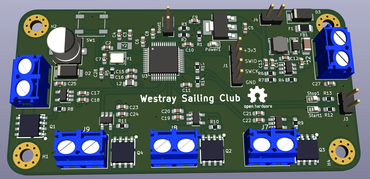
The PCB
Learning KiCad and designing my very first PCBs was a lot of fun. I don’t have any formal education in Electronics, it took a while to get some ideas about using the software and making something useful out of it.
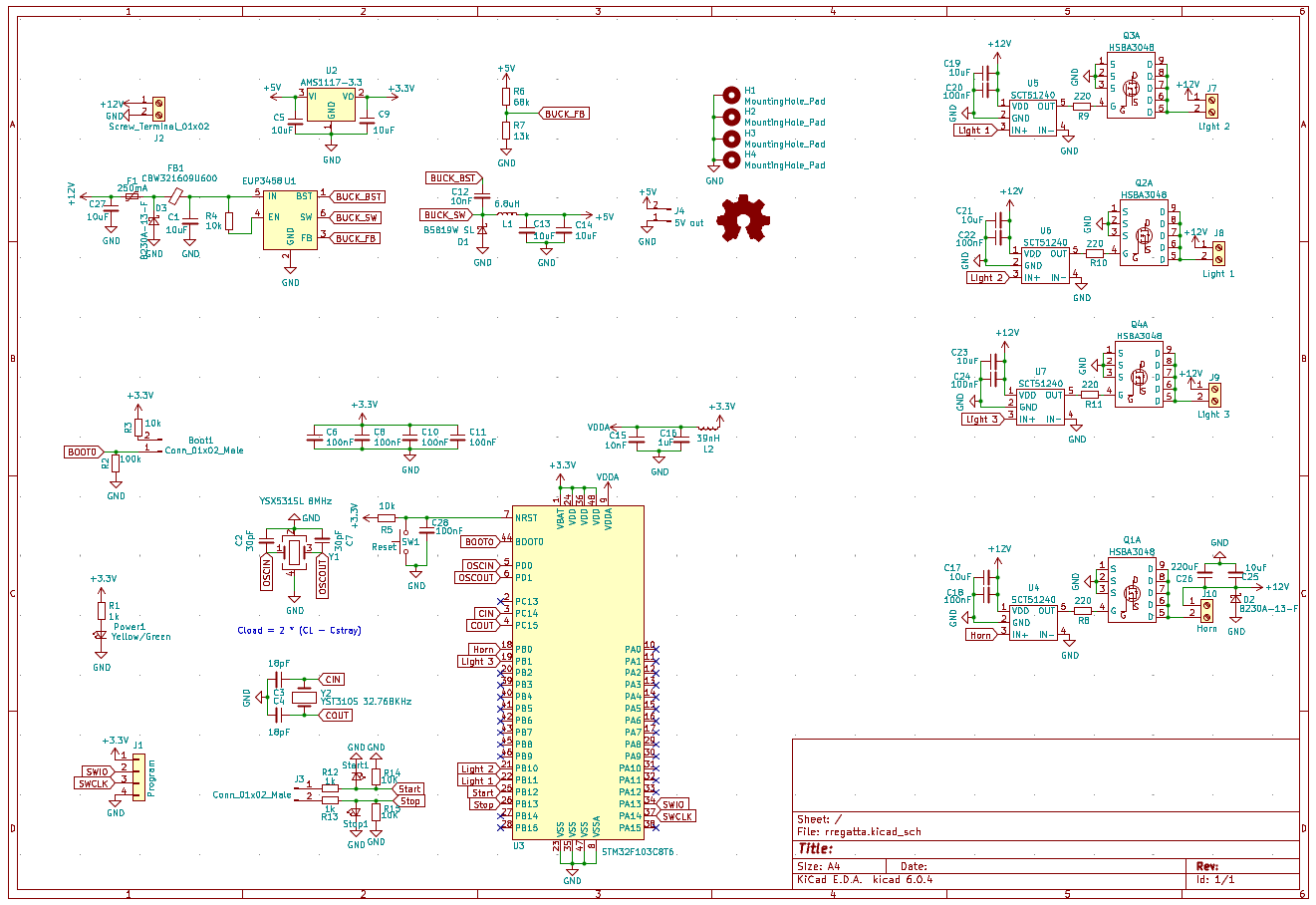
Board Schematic
I’m glancing over a lot of details about the PCB, as I don’t feel that I’m in a position to provide much value, since I’m an absolute beginner in this field. However gist of the process is that you draw a schematic and logically place all your components and wire them up virtually in KiCad . Then the tool helps design your PCBs physical layout. There were a lot of component footprints I had to manually design so the they can be soldered with their precise measurements.
I learned a lot about, basic electronics, drawing schematics, minimum circuit required for each IC/Chip and read a lot about almost every single part used in this board. I will discuss a few of the design decisions I made, here in this post, but discussing all of it would be very lengthy to say the least.
Power Supply
First things first, we need clean 3.3v source to power the MCU and 5v source to power an external radio receiver for remote operations (see below in Action). Current requirements I had two options, linear step down conversion or a more efficient switching power supply buck converter circuit.
I decided use switching buck converter for steeping down from 12v to 5v for the start/stop signals and external radio receiver, and a simple linear step down converter from 5v to 3.3v to power the MCU since it is a much smaller design and power requirements are well under what converter can provide. I used a AMS1117-3.3 IC for this job.

If you are new to electronic circuits, getting used to reading the component datasheets is the most valuable skill you can have. Sometimes datasheets are very long (yet incomplete) and full of jargon. But once you get used to it you would be able to skim and find the relative information very quickly for the most part.
I used EUP3458 as my step down DC-DC convertor, if you look at the datasheet here it actually gives you a full example circuit for how to use the chip to make a 5v step down convertor.
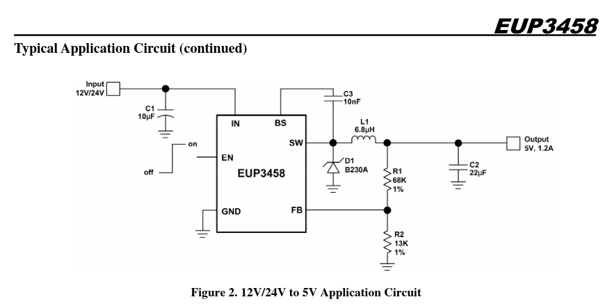
Example Schematic EUP3458 5v step down converter
There are minor changes that I made i.e. I need this to be on all the time, so I supply direct voltage to EN pin via a resistor instead of a switch as shown in pictured above.
Many of you who are electrical engineers will find flaws in my design, I seek your forgiveness and welcome any suggestions either via email or twitter links on this page.
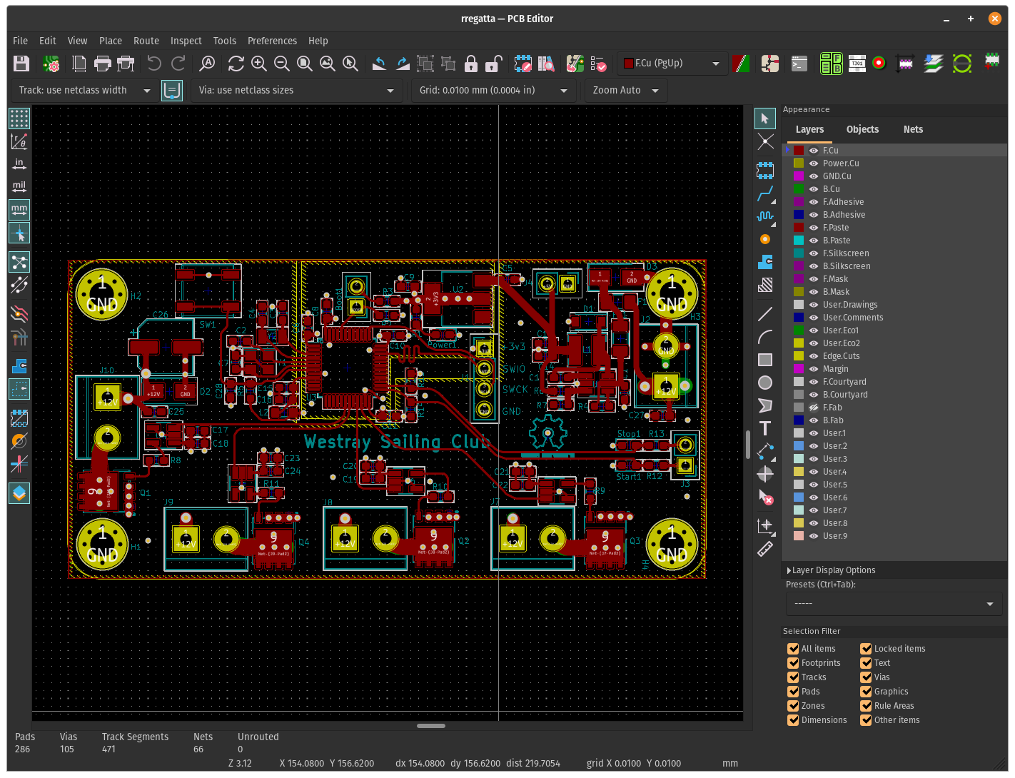
Layout of the PCB
Once I had the design, I checked everything from datasheet to schematics to layout, again and again, made tweaks, corrected blunders that could potentially end up in fireworks. I made the order for fabrication and waited for a few weeks for the PCBs to arrive, and they finally showed up.
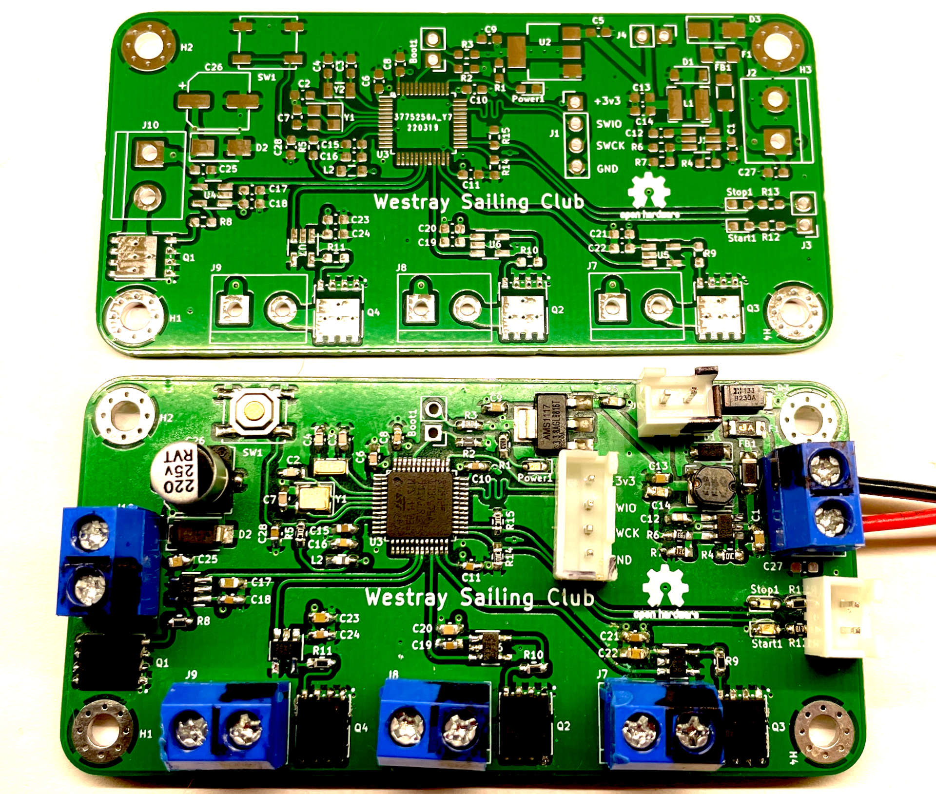
Populating the PCB by hand is not perfect, but it does the job
Schema and PCB files are
here
(GPL License). In addition to the custom PCB I also used off the shelf 433Mhz RF Module and a remote, this allowed me to mimic the hardware switches/buttons with the remote.
Button operations, using a LED Array instead of horn. (single beep for start and double beep for cancel indication)
While designing this board I stumbled upon this great lecture How to Achieve Proper Grounding - Rick Hartley - Expert Live Training (US) . It is more than 2 hours long, but discusses a lot of fundamentals of electronics and PCB design, Highly Recommended.
Firmware
This is what started my entire journey into embedded systems, that I wanted to write rust and run away as far as possible from the Front End development (no offence intended to FE devs). Rust has great support for ARM microcontrollers. For Blue Pill class of Microcontrollers there is this fantastic hardware abstraction layer (HAL) implementation
stm32f3xx-hal
with a lot of examples. Since the requirements for this project are rather simple, it would be very easy to do an Arduino style setup/loop implementation.
While I was working on another bit more complex project, I stumbled upon RTIC that stands for Real-Time Interrupt-driven Concurrency. Instead of using a busy loop and polling/updating state RTIC allows you to use timer Interrupts, that can spawn a specific task at a specific time or event. A task can do its job and exit or it can trigger another task (including itself) immediately or at a time interval.
RTIC Overview
RTIC is a rust framework for embedded devices, I have only used it on ARM chips, not sure if it works properly on other platforms. It allows you to structure your program based upon time based and other interrupts to perform certain tasks. If you are familiar with Arduino, a simplest example would be to turn on and off an LED every one second, for this you’d find numerous examples with the use of delay functions (keeping the CPU busy for a certain amount of time or cycles). Since most MCUs are single core architectures, you cannot do anything else but to wait for the time/cycles to finish before anything else can be done. With interrupts driven approach, you set up a kind of reminder and wake up a portion of code when the interrupt happens i.e enough time has passed. Best thing is you are free to perform any other tasks or even put the CPU to sleep in the mean time. I found that manually setting up timers and interrupts is tedious to say the least. This is where RTIC comes in, it makes it much easier to create small amount of work as tasks, configure and execute them with much ease. In my other project I have used USB interrupts to do stuff only when you send data over the USB, otherwise you are free to perform regular computation that MCUs is supposed to do as its main job. The biggest benefit of this approach is that you don’t need a busy loop to check for all the possible scenarios ie. constantly checking if USB Serial has some incoming data etc.
Here though we are going to only use time based interrupts, since that’s all we really need to build a timer. Before we dig into the code for this project, let’s have quick look at some of the key concepts of RTIC.
Everything is defined within a module annotated with
#[rtic::app(...)], The app attribute has a mandatory device argument that takes a path as a value.A Task is just a function that performs, well a task, and can use shared or local variables. There can be arbitrary number of tasks, with at least one that is required with annotate with
#[init]attribute.inittask must havefn(init::Context) -> (Shared, Local, init::Monotonics)signature and is used to initialize hardware and local/shared state.initis only called once after the system reset. There is also aidletask withfn(idle::Context) -> !signature, that is auto defined unless explicitly, idle loops forever much like Arduinoloop, you are not required to use it or it can just be used to put the CPU to sleep when there is nothing else to do.RTIC has two types of state,
SharedandLocal, as the name impliesLocalstate can be used by one and only one task and will be available to it via theContext, whereas multiple tasks can used shared state via theContextas well but it implements a Mutex trait so only one task at a time can have access to its internal data. Additionally if you don’t need to initialize state with something with the HAL , you can define local state at the task level with annotation.
Checkout https://rtic.rs for much deeper dive of RTIC concepts and examples.
Rust Project Setup
I use following tools to work with stm32 arm based devices, mainly from ferrous-systems’
Knurling project tools
. If you are not familiar, knurling gives you grip on bare metal (I love this fun name).
- probe-run , A custom Cargo runner that transparently runs Rust firmware on an embedded device.
- cargo-flash , Provides a cargo subcommand to flash ELF binaries onto ARM chips.
- flip-link , Adds zero-cost stack overflow protection to your embedded programs.
Check out knurling project's app-templates and use cargo-generate for a much easier time to setup a new project.
# install the required tools
cargo install probe-run cargo-flash flip-link
# Cargo.toml
[package]
name = "rregatta32"
version = "1.0.0"
edition = "2021"

[dependencies]
cortex-m = "0.7"
cortex-m-rtic = "1.1"
defmt = "0.3"
defmt-rtt = "0.3"
embedded-hal = "0.2"
oorandom = "11.1"
panic-probe = { version = "0.3", features = ["print-defmt"] }
stm32f1xx-hal = { version = "0.9", features = ["rt", "stm32f103"] }
systick-monotonic = "1.0"

# cargo build/run
[profile.dev]
codegen-units = 1
debug = 2
debug-assertions = true
incremental = false
opt-level = 3
lto = 'fat'
overflow-checks = true

# cargo build/run --release
[profile.release]
codegen-units = 1
debug = 2
debug-assertions = false
incremental = false
lto = 'fat'
opt-level = 3
overflow-checks = false
Code
Lets dive in the code for rregatta32, below is how I started building the application.
Setup and Init
After the initial use statements, we define MonotonicTick as monotonic clock ticking at 5000Htz (this number is arbitrary, at least in this case) you could make it tick at up to any rate you like up to supported by your chip. In my case 200 µs granularity is good enough.
Then we define shared resources, as it suggests shared resources can be safely shared between tasks. Later you’ll see that resources like the pins controls of horn and lights can be manipulated by different tasks. Start and Stop pins are defined as Local because there is only ever going to be one task that need access to them.
You may find the pin number chosen here are a bit out of order and strange, this is mostly due to the board layout above. this configuration simply made more sense to me as I was laying out the traces for signals. Start and Stop buttons however use special pins, according to the stm32f103 datasheet pin 25 and 26 are 5v tolerant. Since the signal provided by the 433Mhz RF Module is 5v, using non tolerant pins (3.3v) could permanently damage the MCU.
#![deny(unsafe_code)]
#![deny(warnings)]
#![no_main]
#![no_std]

#[rtic::app(device = stm32f1xx_hal::pac, dispatchers = [RTC, TIM2])]
mod app {
    use defmt::{println, Format};
    use oorandom::Rand64;
    use stm32f1xx_hal::{
        flash::FlashExt,
        gpio::{
            gpiob::{PB0, PB1, PB10, PB11, PB12, PB13},
            GpioExt, Input, Output, PullDown, PushPull,
        },
        rcc::RccExt,
    };
    use systick_monotonic::{
        fugit::{Duration, RateExtU32, TimerInstantU64},
        ExtU64, Systick,
    };

    // A monotonic timer to enable scheduling in RTIC
    #[monotonic(binds = SysTick, default = true)]
    type MonotonicTick = Systick<500>; // 500 Hz / 2 ms granularity

    // shared resources between tasks
    // each resource can be passed to a task selectively
    #[shared]
    struct Shared {
        horn: PB0<Output<PushPull>>,    // 18
        light1: PB11<Output<PushPull>>, // 22
        light2: PB10<Output<PushPull>>, // 21
        light3: PB1<Output<PushPull>>,  // 19
        handel: Option<controller::MonotonicTick::SpawnHandle>,
    }

    #[local]
    struct Local {
        start_button: PB12<Input<PullDown>>, // 25 5V/IO
        stop_button: PB13<Input<PullDown>>,  // 26 5V/IO
    }

    #[init]
    fn init(cx: init::Context) -> (Shared, Local, init::Monotonics) {
        let dp = cx.device; // device peripherals
        let mut flash = dp.FLASH.constrain();
        let rcc = dp.RCC.constrain();
        // Acquire the GPIOB peripheral
        let mut gpiob = dp.GPIOB.split();

        let _clocks = rcc
            .cfgr
            .use_hse(8.MHz())
            .sysclk(32.MHz())
            .freeze(&mut flash.acr);

        // Initialize the monotonic clock based on system timer running at 32Mhz
        // (see _clocks)
        let mut mono = Systick::new(cx.core.SYST, 32_000_000);

        let start_button = gpiob.pb12.into_pull_down_input(&mut gpiob.crh);
        let stop_button = gpiob.pb13.into_pull_down_input(&mut gpiob.crh);

        let horn = gpiob.pb0.into_push_pull_output(&mut gpiob.crl);
        let light1 = gpiob.pb11.into_push_pull_output(&mut gpiob.crh);
        let light2 = gpiob.pb10.into_push_pull_output(&mut gpiob.crh);
        let light3 = gpiob.pb1.into_push_pull_output(&mut gpiob.crl);

        reset_all::spawn().ok();

        // spawn task to periodically check button state
        poll_buttons::spawn(mono.now()).ok();

        (
            Shared {
                handel: None,
                horn,
                light1,
                light2,
                light3,
            },
            Local {
                start_button,
                stop_button,
            },
            init::Monotonics(mono),
        )
    }
// ....snip
//
}
init as the name suggests, initialises all resources along with configuring the MCU as needed. I have used an external 8MHz crystal in the design of this board, therefore I configure MCU to use the hse (High Speed External) clock set at 8MHz. System Clock is set to 32 MHz and that is used to create the Monotonic Timer running at the same tick speed. Rest of the code is to configure and initialize the pins. Button pins are pull down input, that just means that they respond to input voltage with the default state being low (pulled down to ground). Pins to control the mosfet drivers are configured as output pins (obviously) in push pull configuration. Snippet above won’t work on its own as we still need to define various tasks that are called and spawned here.
For more use cases, see official stm32f1xx-hal
examples
Start/Stop task
We want to start the timer sequence when the start button is pressed (or pulled high by the RF Module) and timer is not already running, and subsequently stop when the button is pressed if timer IS running.
#[rtic::app(device = stm32f1xx_hal::pac, dispatchers = [RTC, TIM2])]
mod app {
    /// ... snip
    /// periodic task to check buttons
    #[task(priority=2, local = [count: u64 = 0, start_button, stop_button], shared = [handel])]
    fn poll_buttons(
        mut cx: poll_buttons::Context,
        instant: TimerInstantU64<500>,
    ) {
        let poll_buttons::LocalResources {
            start_button,
            stop_button,
            count,
        } = cx.local;

        // up the tick count by one
        *count = count.wrapping_add(1);

        cx.shared.handel.lock(|handel| {
            if stop_button.is_high() {
                if let Some(h) = handel.take() {
                    defmt::println!("Stopping");
                    reset_all::spawn().ok();
                    if h.cancel().is_ok() {
                        defmt::println!("stopped");
                        beep_horn::spawn_after(100.millis(), 300.millis(), 2).ok();
                    } else {
                        defmt::println!("Something went wrong");
                    }
                }
            } else if start_button.is_high() && handel.is_none() {
                defmt::println!("spawning");
                *handel = controller::spawn_at(
                    monotonics::now(),
                    instant,
                    State::Warmup,
                    *count,
                )
                .ok();
            }
        });
        // Periodic check buttons every 50ms
        poll_buttons::spawn_at(instant, instant + 50.millis()).ok();
    }
/// ... snip
}
In the poll_buttons task below, we lock the shared resource handle that is a task handle for the controller task (more on that later) and check both button state, if stop button is pressed we spawn reset_all task and and cancel the timer task if it is running, beep the horn for 300ms twice, to give the sailors an audible clue that the timer has been cancelled.
If start button is pressed and timer handle is None we spawn it and give it a monotonic instant of now. This implementation doesn’t require us to debounce the button press since we do not repeat the already running state i.e we only start if not started or stop if not already stopped.
You may have noticed that this task defines an additional local state count that is not part of the global Local struct. rtic allows for this, its fine to define the local state here since it doesn’t need to be initialized using hal peripherals. count is then passed on to the controller task that will use this as a seed to generate a pseudo random time frame between warmup horn and three minute count start.
Helper Tasks
We have three helper tasks reset_all, set_lights and beep_horn, as the name suggests they perform simple actions i.e turn off all lights and horn, set the light state with given value for each of them and beep the horn for given amount and number of of times. To repeat the beep horn we re spawn the task from within while keeping track of the horn state and a count of the beeps. I really like this powerful feature of rtic that you can do this without the need of manually setting up timer interrupts and/or consuming resources with a busy loop to represent a delay. This is a very simple project but it can be very useful if you have a busy schedule for the MCU to do.
You may have noticed that helper tasks have priority=1 but poll_button had priority=2 according to rtic
documentation
A higher number means a higher priority in RTIC, which is the opposite from what Cortex-M does in the NVIC peripheral. Explicitly, this means that number 10 has a higher priority than number 9.
I also noticed that you need more than one dispatchers (RTC and TIM2 in this case) if you want to have multiple levels of priorities for the tasks in use, otherwise rustc 🦀 gets mad.
#[rtic::app(device = stm32f1xx_hal::pac, dispatchers = [RTC, TIM2])]
mod app {
    /// ... snip
        #[task(priority=1, shared = [horn, light1, light2, light3])]
    fn reset_all(cx: reset_all::Context) {
        let reset_all::SharedResources {
            horn,
            light1,
            light2,
            light3,
        } = cx.shared;

        (horn, light1, light2, light3).lock(|horn, light1, light2, light3| {
            defmt::println!("Reset all");
            horn.set_low();
            light1.set_low();
            light2.set_low();
            light3.set_low();
        });
    }

    #[derive(Format, Debug)]
    pub enum Light {
        On,
        Off,
    }

    /// set light status with a small delay in between
    #[task(priority=1, shared = [light1, light2, light3])]
    fn set_lights(cx: set_lights::Context, l1: Light, l2: Light, l3: Light) {
        let set_lights::SharedResources {
            light1,
            light2,
            light3,
        } = cx.shared;

        (light1, light2, light3).lock(|light1, light2, light3| {
            defmt::println!("Setting lights 1:{} 2:{} 3:{}", l1, l2, l3);

            match l1 {
                Light::On => light1.set_high(),
                Light::Off => light1.set_low(),
            }
            match l2 {
                Light::On => light2.set_high(),
                Light::Off => light2.set_low(),
            }
            match l3 {
                Light::On => light3.set_high(),
                Light::Off => light3.set_low(),
            }
        });
    }

    /// set horn state high for given milliseconds
    #[task(priority=1, local = [is_high: bool = false], shared = [horn])]
    fn beep_horn(mut cx: beep_horn::Context, duration: Duration<u64, 1, 500>, times: i8) {
        if !*cx.local.is_high {
            *cx.local.is_high = true;
            cx.shared.horn.lock(|horn| {
                println!("horn START");
                horn.set_high();
            });
            beep_horn::spawn_after(duration, duration, times - 1)
                .ok();
        } else {
            *cx.local.is_high = false;
            cx.shared.horn.lock(|horn| {
                println!("horn STOP");
                horn.set_low();
            });
            // spawn again if times are left
            if times > 0 {
                beep_horn::spawn_after(50.millis(), duration, times - 1)
                    .ok();
            }
        }
    }

    #[idle]
    fn idle(_cx: idle::Context) -> ! {
        loop {
            // Now Wait For Interrupt is used instead of a busy-wait loop
            // to allow MCU to sleep between interrupts
            // https://developer.arm.com/documentation/ddi0406/c/Application-Level-Architecture/Instruction-Details/Alphabetical-list-of-instructions/WFI
            rtic::export::nop()
        }
    }
    /// ... snip
}
Controller Task
controller task is like a state machine, it would act differently depending on the state that its in. Our time measurement is in minutes so second based granularity works just fine. re_spawn closure takes the next state
and time in seconds when the next state should be spawned at. If the task is interrupted (stopped) at any point since we store its handle in the shared resource, it can be cancelled and discarded safely.
Warmup state runs for a pseudo random amount of time, between 20 and 60 seconds. This not very secure way of generating radomness but it good enough that, a sailor can’t easily replicate it if they ever have to operate it themselves.
#[rtic::app(device = stm32f1xx_hal::pac, dispatchers = [RTC, TIM2])]
mod app {
    /// ... snip
    /// State of the race timer each variant is used to perform a specific
    /// operation and trigger next next task with a new state.
    #[derive(Debug, Clone, Copy, Format)]
    pub enum State {
        Warmup,
        Three,
        Two,
        One,
        Start,
    }

    #[task(priority=1, shared = [handel])]
    fn controller(
        mut cx: controller::Context,
        instant: TimerInstantU64<500>,
        state: State,
        seed: u64,
    ) {
        use State::*;

        defmt::println!("State {:?}", state);

        // re-spawn self with given state and time (seconds from now)
        let mut re_spawn = |state: State, duration: Duration<u64, 1, 500>| {
            cx.shared.handel.lock(|handel| {
                defmt::println!("spawning {:?}", state);
                *handel = controller::spawn_at(
                    instant + duration,
                    instant + duration,
                    state,
                    seed,
                )
                .ok()
            });
        };

        match state {
            Warmup => {
                // horn for 800ms once
                beep_horn::spawn(800.millis(), 1).ok();

                defmt::println!("Seed {}", seed);
                let random = Rand64::new(seed.into()).rand_range(30..60);
                defmt::println!("Warmup period: {}secs", random);

                re_spawn(Three, random.secs());
            }
            Three => {
                beep_horn::spawn(1200.millis(), 1).ok();
                set_lights::spawn_after(
                    100_u64.millis(),
                    Light::On,
                    Light::On,
                    Light::On,
                )
                .ok();
                re_spawn(Two, 1.minutes());
            }
            Two => {
                beep_horn::spawn(400.millis(), 1).ok();
                set_lights::spawn_after(
                    100_u64.millis(),
                    Light::Off,
                    Light::On,
                    Light::On,
                )
                .ok();
                re_spawn(One, 1.minutes());
            }
            One => {
                beep_horn::spawn(400.millis(), 1).ok();
                set_lights::spawn(Light::Off, Light::Off, Light::On).ok();
                re_spawn(Start, 1.minutes());
            }
            Start => {
                beep_horn::spawn(2000.millis(), 1).ok();
                set_lights::spawn(Light::Off, Light::Off, Light::Off).ok();
                defmt::println!("Start !!!!!!!!!!!!!!");
                cx.shared.handel.lock(|handel| *handel = None);
            }
        }
    }
}
Potential bugs and error handling
There is some amount of error handling but, there is still a potential for buggy behaviour, i.e if any of the task that we don’t store the handle for therefore cannot check if it is already spawned, can panic if we try to re-spawn it. It has not come up with the testing I have done so far since most of the tasks are sequential, if it does I’ll be taking my laptop to the pier and debugging it in production ;)
Improvements
I asked on the #rtic:matrix.org channel for review of the above design and got some valuable feedback from
Emil Fresk
, one of the RTIC maintainers.
- Flyback DIODs were missing to protect the mosfets from inductive load reverse current flow (I will update the schematic and pcb layout accordingly).
- Buck convertor design could be improved, to reduce potential EMI (see below).
- Original
Systic<5000>had a too high interrupt rate, I reduced it toSystick<500> - Using
unwrap()in embedded environment, greatly interested the bin size as it pulls in formatting bloat. (to my surprise I managed to reduce the bin from27KiBto17KiBusing his tips)
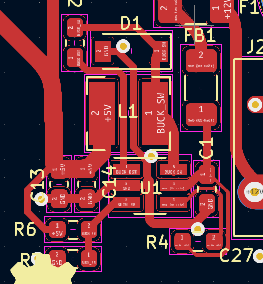
Improved buck convertor layout suggested by Emil Fresk
Conclusion
I’m not really sure what to conclude here, apart from the fact that both electronics and rust are fun. I put this post out for anyone who is currently interested in either of those, to try out the other and have fun while doing it.