For a while I wanted to get back into making some projects with microcontrollers. Last time I touched any microcontroller code was a few years back when I tried to make a heating regulator for a friend with Arduino Nano . My friend was interested in programming, he would come over at night and we hacked on this little thing for some time. We bumped into some problems with the power supply as it would not behave properly when we used a random old DC adapter. Life happened and we lost interest before it could actually be tested. Maybe we were just debugging too late at night, there was some whiskey involved, so who knows..
Anyhoo, recently I wanted to try out embedded rust. After some looking around, PIC32MX series sounded like a good choice for a project I have in mind (more on that later). It has with enough number of IO pins and in built USB support and is a way overkill for blinking a LED.

Disclaimer: This post is for the noobs like me to get started with PIC32 in rust.
This is my first attempt to program a Microcontroller outside of Arduino boards. I have huge gaps in my knowledge abut how these things work. I'm always open to suggestions and discussion, please reply to the threads on Reddit, Mastodon or email me. (If I can stay motivated to learn, I may post more stuff here later)
There are PIC32 development boards like this but I went the bare chip route. It was a less convenient solution but it provides more opportunities to learn tinker. To get started you need a few components and of course a PIC32 microcontroller (at least one 😉).
Following is the bare minimum that you need to write “hello world” (blink an LED).
- Breadboard
- Jumper Wires
- LED
- PIKITTM3 Programmer
- PIC32 (in my case MX270F256B)
- assorted ceramic disk capacitor kit
- assorted resister kit
- push buttons, and other stuff if you want to expand your program (optional)
I recommend getting an inexpensive hobby electronics starter kit that provides a bunch of components like resistors,capacitors and LEDs etc.
According to Wikipedia
A microcontroller (MCU for microcontroller unit) is a small computer on a single metal-oxide-semiconductor (MOS) integrated circuit (IC) chip. A microcontroller contains one or more CPUs (processor cores) along with memory and programmable input/output peripherals. Program memory in the form of ferroelectric RAM, NOR flash or OTP ROM is also often included on chip, as well as a small amount of RAM. Microcontrollers are designed for embedded applications, in contrast to the microprocessors used in personal computers or other general purpose applications consisting of various discrete chips.
So the journey to the rabbit hole started. I came across pic32-rs a carate for rust binding for the PIC. Once my chips arrived in the mail, I was excited to play with them, but I had no idea where to begin. Duckduckgo didn’t give me much result, for whatever reason most of PIC tutorials are old, it seems the interest in PIC slowed down since Arduino and other hundreds of little boards came to the scene. It turns out that, one can figure out a lot just from the PIC32MX family datasheet alone. There is also a user guide to the PIKITTM3 programmer.
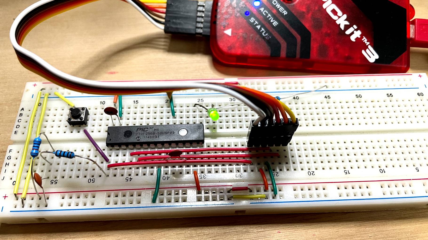
Wiring it all up
I wired up the microcontroller on a breadboard according to the following diagram, as you can see in the featured image above (plus a reset button and LED)
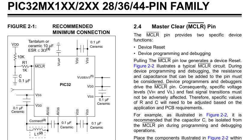
PIC32MX recommended minimum connections
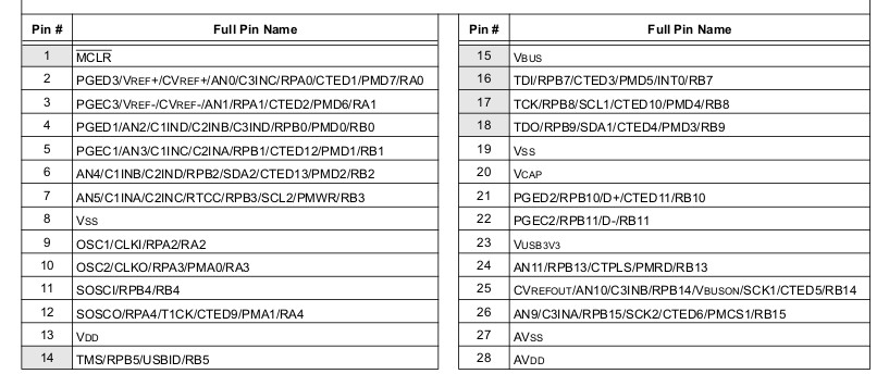
PIC32MX270F256B pinout table
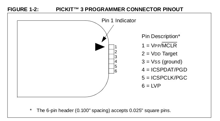
PICKIT3 connector pinout
I had power to the controller and it has the minimum connections required to operate, but how do i flash it. Microchip the company provides a version of their tools MPLAB IDE and MPLAB IPE for Linux. For the love of XXX I couldn’t get it to work for me to even test if my setup is wired correctly. At that point I turned to open-source solutions.
Small hiccups
I cloned the
pic32-rs
crate locally and after following the instructions I was able to compile the blinky example successfully. But when I tried to upload the hex
via MPLAB IPE I would consistently get the following error.
*****************************************************

Connecting to MPLAB PICkit 3...

Currently loaded firmware on PICkit 3
Firmware Suite Version.....01.56.09
Firmware type..............PIC32MX
Target voltage detected
Target device PIC32MX270F256B found.
Device ID Revision = A2
Loading code from /home/.../Projects/pic32-rs/examples/blinky/blinky.hex...
Warning: /home/.../Projects/pic32-rs/examples/blinky/blinky.hex contains code that is located at addresses that do not exist on the PIC32MX270F256B.
Code incompletely loaded starting at 0x9D000000 (0x3D4).
2021-08-20 11:17:58 +0100 - Hex file loaded successfully.
2021-08-20 11:18:06 +0100 - Programming...


Device Erased...

Programming...

The following memory area(s) will be programmed:
MPLAB's memory is blank so no programming operation was attempted.
2021-08-20 11:18:10 +0100 - Programming complete
I asked kiffie the maintainer of the crate, and he explained that
The problem is that objcopy produces hex files having virtual addresses as opposed to physical addresses. It seems that the Microchip programmer can handle hex files having physical addresses only. I did not experience this problem because I use a different programming tool: pic32prog.
According to his suggestion, using xc32-bin2hex on the binary produced by the rust compiler seemed to worked but I still wasn’t able to upload the hex file. Turns out the 10µF ceramic capacitor on pin-20(VCAP) was essential to successfully program a PIC32. Finally it blinked as expected.
Flashing PIKITTM3 to use with pic32prog command line tool
Now I wasn’t happy with firing up a massive Java application just to upload my hex every single time I edited it. I started looking into pic32prog to see if I could make that work. I cloned the repo and built the tool, but it refused to recognize my PIKITTM3 as it required a custom different firmware. Looking into the pic32prog wiki I found
Flashing on Linux using pickit-3
. It requires to have access to windows machine or fire up a windows VM to flash the required firmware. Don’t be too alarmed if the whole thing hangs while flashing and refuses to recognize device, as this happened to me and I’m able to use it just fine. Just to re-iterate with this setup you don’t need MATLAB IDE, simply compile with cargo (project has a handy build.sh script) then flash with pic32prog -p blinky.hex, the -p option will keep the device powered with the PIKITTM3 so you don’t need any external 3.3v source.
What the hell are these hex numbers?
As you can see the blinky/src/main.rs a small program, but as a noob I do not understand fully what is going on there. Very first thing that caught my eye was
// PIC32 configuration registers for PIC32MX1xx and PIC32MX2xx
#[cfg(any(
    feature = "pic32mx1xxfxxxb",
    feature = "pic32mx2xxfxxxb"
))]
#[link_section = ".configsfrs"]
#[no_mangle]
pub static CONFIGSFRS: [u32; 4] = [
    0x0fffffff, // DEVCFG3
    0xfff9ffd9, // DEVCFG2
    0xff7fcfd9, // DEVCFG1
    0x7ffffffb, // DEVCFG0
];
It seems this is the main configuration bits for the configuration registers for pic32mx1xxfxxxb and pic32mx2xxfxxxb family of chips. To get a bit of understanding I converted the values to binary i.e.
0x0fffffff, // DEVCFG3 00001111 11111111 11111111 11111111
0xfff9ffd9, // DEVCFG2 11111111 11111001 11111111 11011001
0xff7fcfd9, // DEVCFG1 11111111 01111111 11001111 11011001
0x7ffffffb, // DEVCFG0 01111111 11111111 11111111 11111011
Sure enough you can see in the datasheet DEVCFG0 has possible values for all the 32 bits defined above. For example bit 31 in reserved to be written as 0 and bit 30-29 should be 1 bit 28 is a code protection bit that 1 means protection is disabled (in our case) but 0 means its enabled. You got the idea here, rest of the configuration is easy to figure out by looking at the datasheet.
Next is the power of the pic32-hal we can use pac::Peripherals::take() to get the Optional struct that can give us access to the peripherals including individual pins of the PIC.
In the blinky program we use the system clock (on PIC32MX270F256B) is clocked at 40Mhz we use this to drive the inbuilt timer to introduce delay for our led blink. 40 MHz system clock is configured by the configuration words (by activating an internal 8 MHz RC oscillator and a PLL )
// setup clock control object
let sysclock = 40_000_000_u32.hz();
let clock = Osc::new(p.OSC, sysclock);
let mut timer = Delay::new(sysclock);
When I reached out to the creator/maintainer of the pic32-rs crate, he kindly answered a few of my questions about how to setup and run for the first time. He also added UART logging to the blinky example since thin would be useful for debugging if you were to expand the example and want to read output/values from the microcontroller to your computer.
Fortunately I had a Serial Module sitting around, I was able to get this working by connecting the usb module’s RX pin to the RB0 AKA PIN 4 of the PIC. To print data form the usb serial device there is a great write up Serial Communication - Discovery on how to set this up.
The communication is done with UART (Universal Asynchronous Receiver Transmitter) built within the PIC. One thing to make note of is that you must use the same buad rate in our case 115200 for both in minicom and when initiating Uart2, otherwise you might get some gibberish printed on the terminal.
Your curios eye might have noticed that there are a couple of files around in the project i.e. 32MX270F256B_procdefs.ld. I did not know anything about it since my encounter with microcontrollers was only through Arduino, so again I asked Kiffie and he replied to me with
This is a linker script fragment that mainly defines the memory layout of the chip. It includes devices.x (part of the Peripheral Access Crate, PAC) and pic32_common.ld (the main part of the linker script). In Arduino, details on linking may not that visible to the user.
Finally here is the simple example. (slightly different than the example in pic32-rs repo)
//! Blinky
//!
//! The classical LED flashing example for a PIC32MX1xx or PIC32MX2xx in a
//! 28 pin package. The clock in generated by the internal RC oscillator. So,
//! no other external parts except the 10 µF capacitor at Vcap (pin 20) and a
//! LED connected via a resistor (e.g. 470 Ohms) to RB7 (pin 16) are needed.
//! RB0 (pin 4) is used to output some text via UART2.

#![no_main]
#![no_std]

use core::{fmt::Write, panic::PanicInfo};

use embedded_hal::{blocking::delay::DelayMs, digital::v2::*};
use mips_rt::{self, entry};
use pic32_hal::{
    clock::Osc, coretimer::Delay, gpio::GpioExt, pac, time::U32Ext, uart::Uart,
};

// PIC32 configuration registers for PIC32MX1xx and PIC32MX2xx
#[cfg(any(feature = "pic32mx1xxfxxxb", feature = "pic32mx2xxfxxxb"))]
#[link_section = ".configsfrs"]
#[no_mangle]
pub static CONFIGSFRS: [u32; 4] = [
    0x0fffffff, // DEVCFG3 00001111 11111111 11111111 11111111
    0xfff9ffd9, // DEVCFG2 11111111 11111001 11111111 11011001
    0xff7fcfd9, // DEVCFG1 11111111 01111111 11001111 11011001
    0x7ffffffb, // DEVCFG0 01111111 11111111 11111111 11111011
];

#[entry]
fn main() -> ! {
    let p = pac::Peripherals::take().unwrap();

    let pps = p.PPS;
    pps.rpb0r.write(|w| unsafe { w.rpb0r().bits(0b0010) }); // U2TX on RPB0

    // setup clock control object
    let sysclock = 40_000_000_u32.hz();
    let clock = Osc::new(p.OSC, sysclock);
    let mut timer = Delay::new(sysclock);

    let uart = Uart::uart2(p.UART2, &clock, 115200);
    timer.delay_ms(10u32);
    let (mut tx, _) = uart.split();
    writeln!(tx, "Blinky example\n").unwrap();

    let parts = p.PORTB.split();
    let mut led = parts.rb7.into_push_pull_output();
    let mut on = true;

    loop {
        writeln!(tx, "LED status: {}", on).unwrap();
        if on {
            led.set_high().unwrap();
        } else {
            led.set_low().unwrap();
        }
        on = !on;
        timer.delay_ms(500u32);
    }
}

#[panic_handler]
fn panic(_panic_info: &PanicInfo<'_>) -> ! {
    loop {}
}
If you want make use of a neatcargofeature, you could edit the/.cargo/configfile and addrunner = "./flash.sh"thencargo runcommand will build and flash the device.
I am planning to explore the USB example next, until then…